Hi-Shear Inst. & Removal l Hand Tool l HLH311
|
Hand Installation Tool Ordering Information Ordering Information |
||
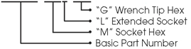
| Part Number Example HLH311-250E-078 |
|||
 |
 |
|
“M” Socket Hex (Matches Collar Driving Hex) |
“G” Wrench Tip Hex (Matches Pin Recess hex) |
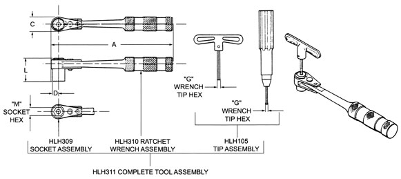
Complete Tool Assy. Part Number |
Dimensions |
Ratchet Wrench Assy. Part No. |
Socket Assembly Part No. |
Wrench Key Assembly part No. |
|||
A |
L |
C |
D |
||||||
1/4” |
5/64” |
HLH311-250E-078 |
6.40 |
0.750 |
0.562 |
0.281 |
HLH310-1 |
HLH309-250E |
HLH105-078 |
HLH311-250F-078 |
1.75 |
HLH310-1 |
HLH309-250F |
HLH105-078 |
|||||
5/16” |
HLH311-312E-078 |
0.750 |
HLH310-1 |
HLH309-312E |
HLH105-078 |
||||
HLH311-312H-078 |
1.375 |
HLH310-1 |
HLH309-312H |
HLH105-078 |
|||||
HLH311-343E-078 |
0.750 |
HLH310-1 |
HLH309-343E |
HLH105-078 |
|||||
11/32” |
3/32” |
HLH311-343E-094 |
HLH310-1 |
HLH309-343E |
HLH105-094 |
||||
HLH311-343H-094 |
1.375 |
HLH310-1 |
HLH309-343H |
HLH105-094 |
|||||
HLH311-437E-094 |
0.750 |
HLH310-1 |
HLH309-437E |
HLH105-094 |
|||||
7/16” |
HLH311-437G-094 |
0.875 |
0.750 |
0.375 |
HLH310-2 |
- |
HLH105-094 |
||
HLH311-437C-094 |
1.500 |
HLH310-2 |
- |
HLH105-094 |
|||||
HLH311-437C-094 |
1.750 |
HLH310-2 |
- |
HLH105-094 |
|||||
1/8” |
HLH311-437E-125 |
0.750 |
HLH310-2 |
- |
HLH105-125 |
||||
1/2” |
5/32” |
HLH311-500G-156 |
0.875 |
HLH310-2 |
- |
HLH105-156 |
|||